8051 Interrupts Explained: Software, Hardware, Vectors, Priorities
The 8051 microcontroller’s interrupt system is one of its most powerful features, letting a tiny chip respond to events without constantly polling the hardware. Whether you’re juggling timer overflows, serial data, or external triggers, understanding how software and hardware interrupts, vector locations, and priority bits work together can make the difference between a jittery prototype and a reliable product. Below we break down each piece of the puzzle, show how they fit in a typical program, and point out the pitfalls that trip up even seasoned developers.
Software Interrupts on the 8051
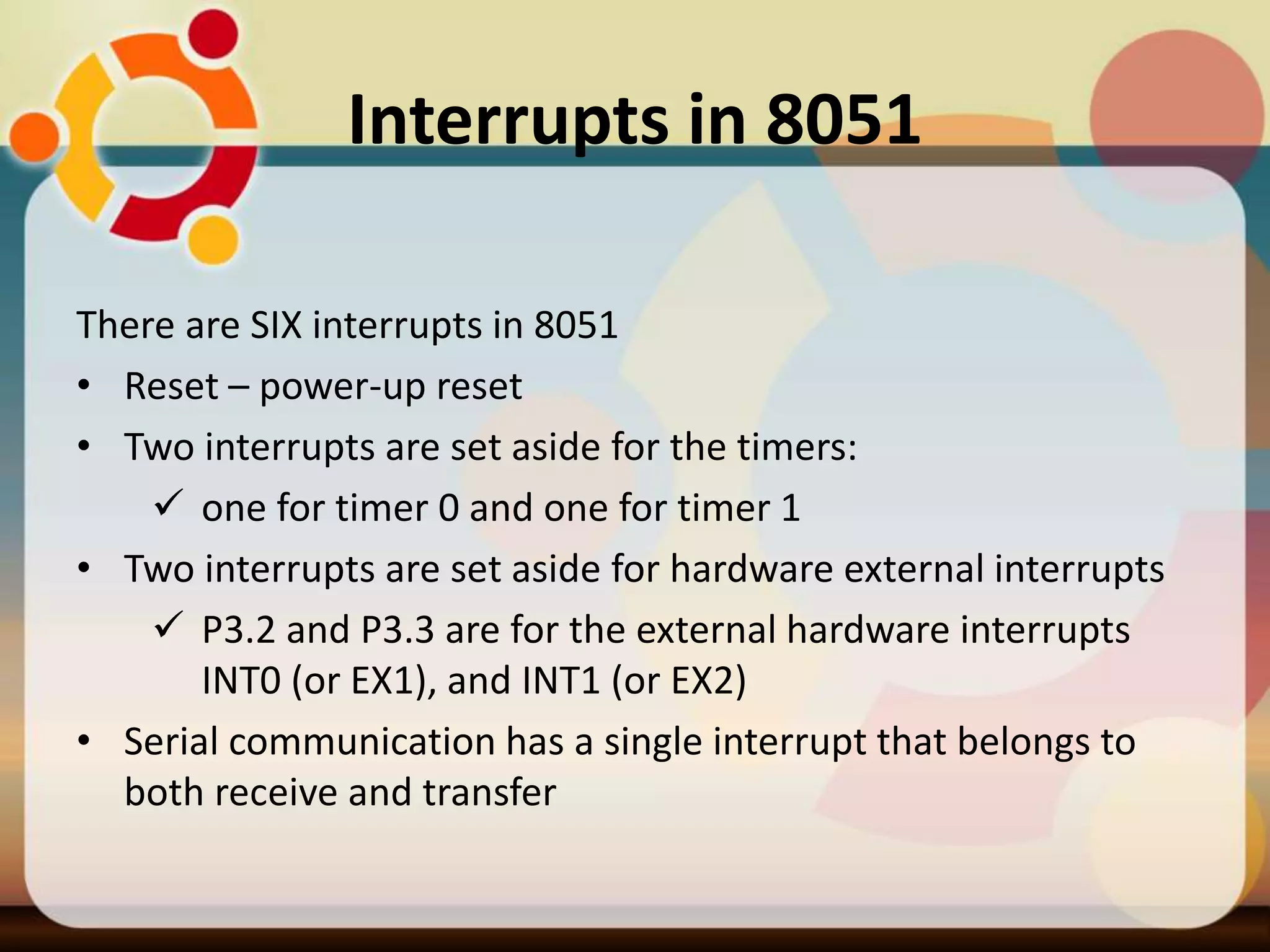
Software‑generated interrupts are essentially flags that the CPU sets internally, usually through special function register (SFR) writes. The most common software interrupt sources are the two timers and the serial port. By setting the appropriate enable bits in IE (Interrupt Enable) and the global EA (Enable All) flag, the processor will jump to the corresponding service routine the next time the flag is raised.
- Timer 0 overflow – controlled by TF0 in TCON.
- Timer 1 overflow – controlled by TF1 in TCON.
- Serial receive – indicated by RI in SCON.
- Serial transmit – indicated by TI in SCON.
Because these flags are cleared automatically (or manually by the ISR), the CPU can handle a burst of events with minimal overhead, freeing the main loop to perform other work.
Hardware Interrupt Mechanism
The 8051 also offers two true external interrupts, INT0 (P3.2) and INT1 (P3.3). Unlike software flags, these pins react to physical signals on the chip’s I/O lines. The TCON register lets you choose between edge‑triggered (a single falling edge) and level‑triggered (low level) operation via the IT0 and IT1 bits.
When the selected condition occurs, the microcontroller instantly suspends the current instruction stream, saves the program counter, and jumps to the interrupt vector associated with the pin. Because the external pins are shared with other I/O functions, designers often add pull‑up resistors or debounce circuitry to avoid false triggers.
Interrupt Vectors and Memory Layout
Every interrupt source on the classic 8051 has a fixed address in program memory where the CPU expects to find the service routine. These are called interrupt vectors, and they occupy the first 32 bytes of code space:
- 0x0003 – External Interrupt 0 (INT0)
- 0x000B – Timer 0 Overflow
- 0x0013 – External Interrupt 1 (INT1)
- 0x001B – Timer 1 Overflow
- 0x0023 – Serial Port Interrupt
Because the vectors are hard‑wired, the usual practice is to place a short jmp or ljmp at each address that redirects to a more spacious routine elsewhere in flash. This keeps the vector table tidy and allows you to change the ISR location without touching the low‑level addresses.
Priority Levels and How They Interact
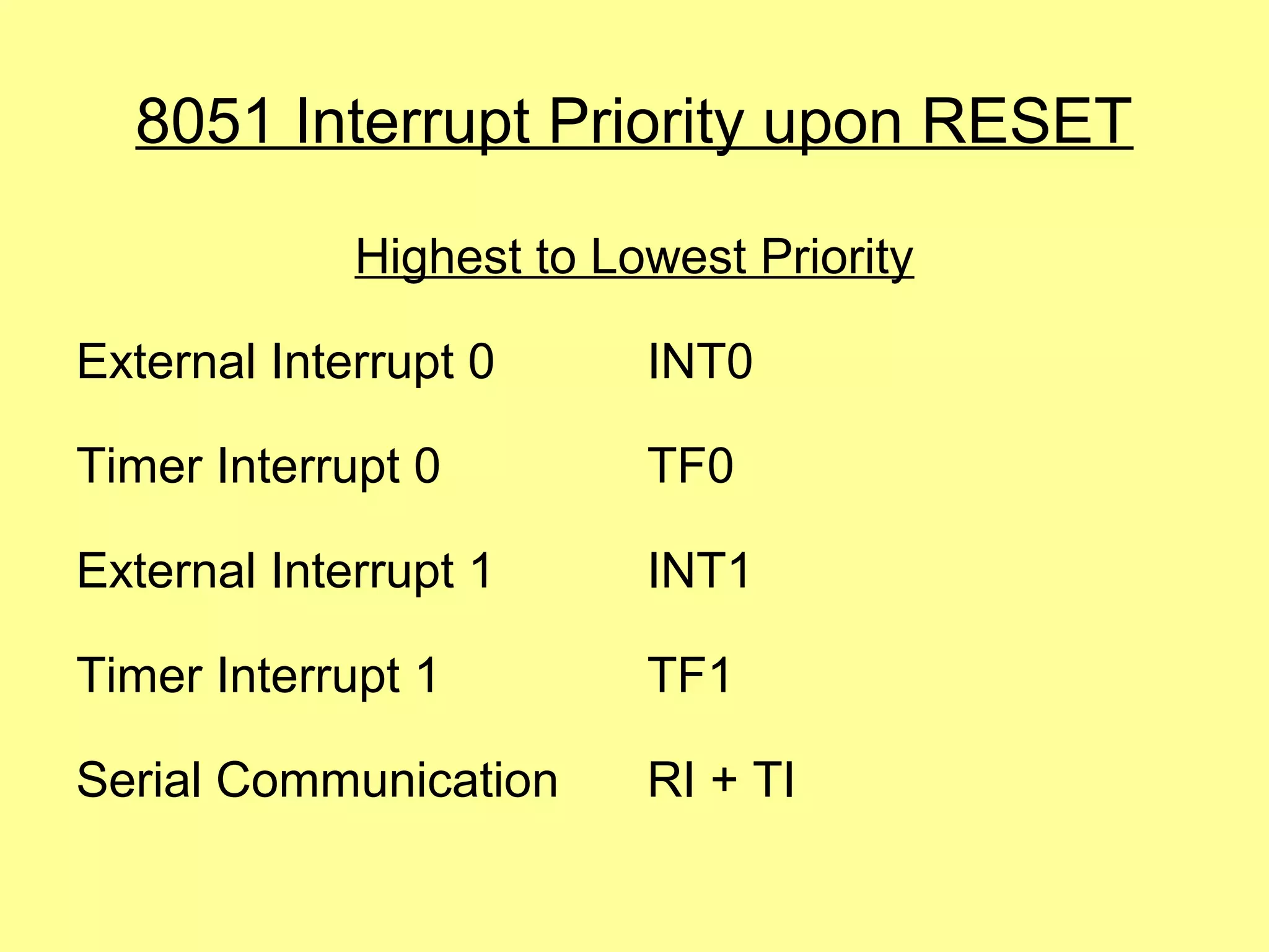
Not all interrupts are created equal. The 8051 includes an IP (Interrupt Priority) register that lets you assign “high” or “low” priority to each source. When two enabled interrupts become pending simultaneously, the high‑priority one wins and the CPU services it first. If an ISR is already running and a higher‑priority interrupt arrives, the processor will automatically nest the new ISR, provided the current ISR has not disabled further nesting by clearing EA.
By default, all interrupts start with low priority. Setting a bit in IP (e.g., PX1 for Timer 1) promotes that source to high priority. Keep in mind that excessive nesting can quickly exhaust the stack, especially on the original 128‑byte internal RAM.
Practical Steps to Configure an Interrupt
Below is a concise checklist you can follow when adding a new interrupt to an 8051 project:
- Identify the source (timer, serial, INT0, INT1).
- Enable the global flag:
EA = 1; - Set the source‑specific enable bit in IE (e.g.,
ET0 = 1;for Timer 0). - If needed, configure the source (mode, reload values, edge/level selection).
- Optionally raise the priority in IP (e.g.,
PX0 = 1;). - Place a
ljmpat the vector address that points to your ISR. - Inside the ISR, clear the interrupt flag (e.g.,
TF0 = 0;) and exit withRETI.
Following this order helps avoid the classic “interrupt never fires” or “CPU hangs in ISR” problems.
Common Mistakes to Avoid
- Forgetting to clear the flag – If the ISR leaves the flag set, the processor will re‑enter the ISR immediately after
RETI, creating an endless loop. - Neglecting stack space – Each nested interrupt consumes two bytes of the internal RAM stack; deep nesting on a tiny stack can corrupt data.
- Mixing edge and level triggers – Using level‑triggered external interrupts without proper debounce can cause the ISR to fire continuously.
- Overlooking the EA bit – Setting individual enable bits without turning on the global flag leaves the interrupt disabled.
Frequently Asked Questions
Can I use the same ISR for multiple interrupt sources?
Yes, but you must check the relevant flag inside the routine to determine which source actually triggered it. This approach saves code space but adds a few extra cycles to the ISR.
What happens if two high‑priority interrupts occur at the same time?
The 8051 hardware arbitrates based on the order of the vector table: the lower‑addressed vector wins. In practice, designers avoid such scenarios by assigning distinct priorities or by handling one source in software.
Is it possible to change an interrupt’s priority at runtime?
Absolutely. The IP register is writable, so you can raise or lower a priority on the fly, for example to give a critical communication channel precedence during a firmware update.
Do modern 8051 derivatives still use the same vector addresses?
Most compatible cores retain the original vector layout, but some enhanced families add extra vectors or allow remapping. Always check the datasheet for your specific part.