How to Set Up a GPIO Interrupt on ESP32 Using IDF
When working with the ESP32 IDF GPIO interrupt mechanism, you quickly discover how powerful event‑driven programming can be. Instead of constantly polling a pin, the processor sleeps until a change on a pin wakes it up, saving energy and keeping the code tidy. Below is a step‑by‑step walk‑through that shows how to configure a pin, write a safe ISR, and test the whole setup with the official ESP‑IDF.
Why Use GPIO Interrupts on the ESP32?
The ESP32’s dual‑core architecture and built‑in low‑power modes make it a natural fit for interrupt‑driven designs. A button press, a sensor pulse, or a communication‑line toggle can instantly trigger a callback without burdening the main loop. This approach is especially valuable in battery‑operated wearables or IoT nodes where every milliwatt counts.
Prerequisites and Development Environment
- ESP‑IDF version 5.x (the latest stable release is recommended)
- A development board such as the ESP‑32 DevKitC
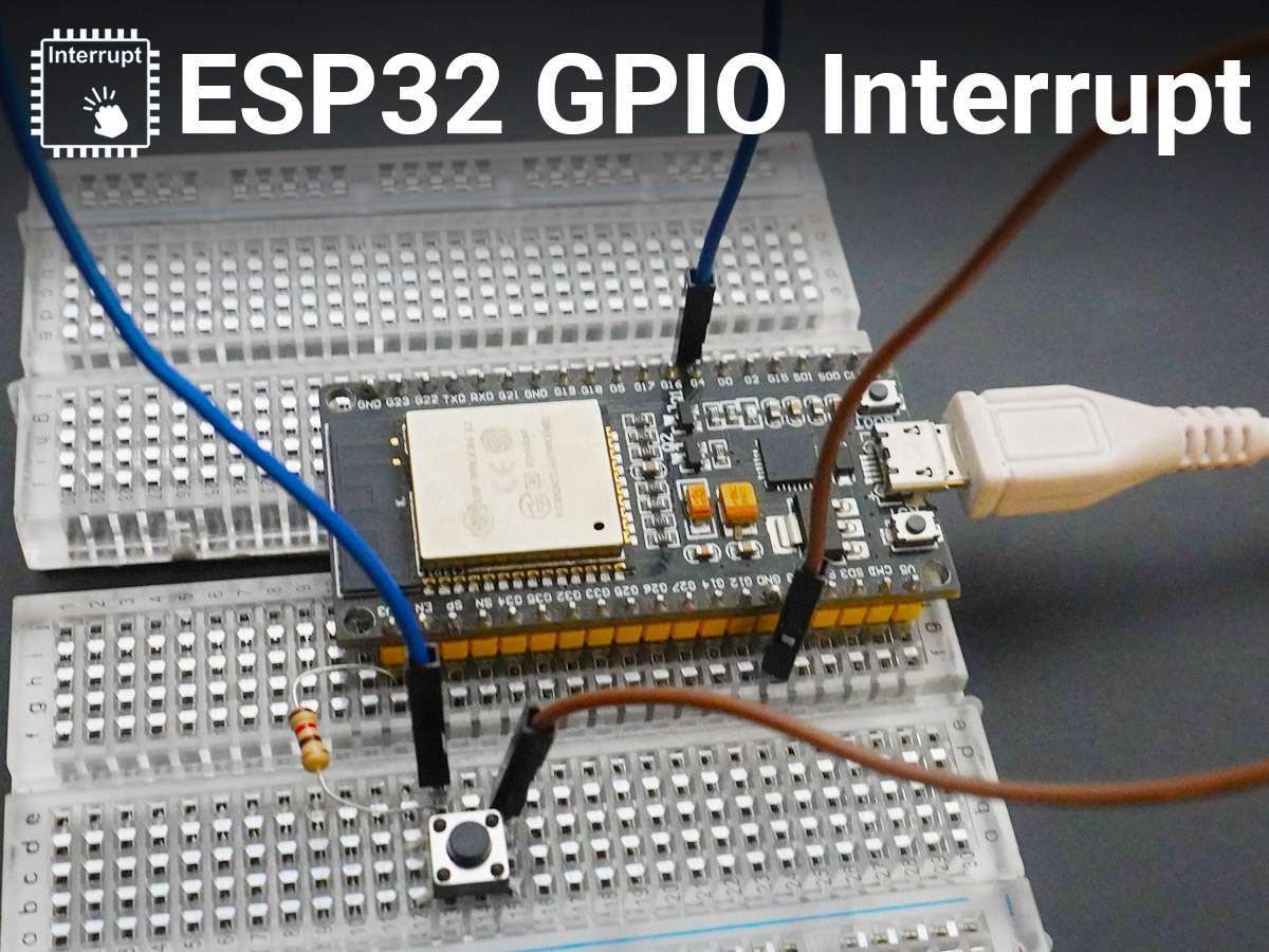
- Serial‑to‑USB cable, a push‑button or any signal source for the GPIO
- Basic familiarity with C and FreeRTOS concepts
Start by cloning the ESP‑IDF repository and running idf.py set-target esp32. The example below assumes you are using idf.py menuconfig to enable the Component config → ESP32 specific → GPIO ISR options, which are on by default.
Configuring the GPIO Pin for Interrupts
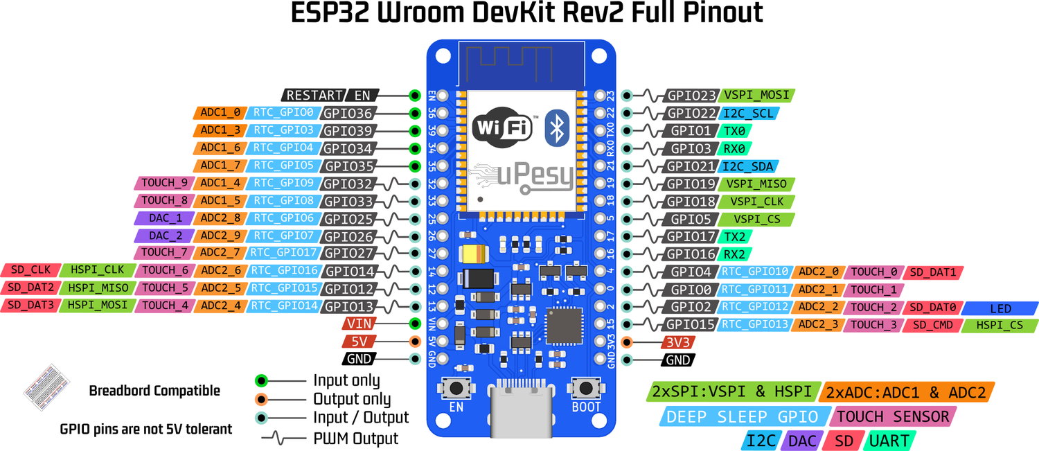
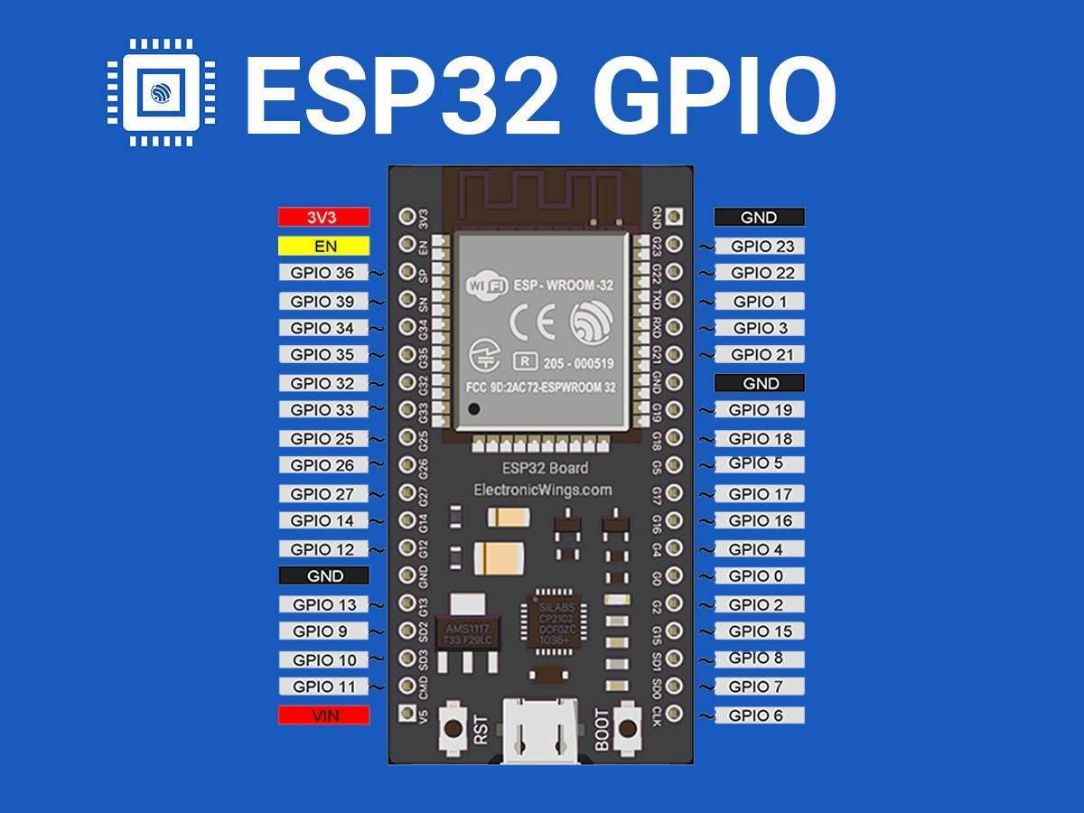
First, pick a pin that is not tied up by the flash or bootloader. GPIO 0, 2, 4, 12, and 15 are common choices. The following snippet shows the essential calls:
gpio_config_t io_conf = {.intr_type = GPIO_INTR_NEGEDGE, // Trigger on falling edge
.mode = GPIO_MODE_INPUT,
.pin_bit_mask = (1ULL << BUTTON_GPIO), // Replace with your pin number
.pull_up_en = GPIO_PULLUP_ENABLE,
.pull_down_en = GPIO_PULLDOWN_DISABLE,
};
gpio_config(&io_conf);
Notice the intr_type field – you can select GPIO_INTR_POSEDGE, GPIO_INTR_ANYEDGE, or level‑triggered variants depending on the hardware signal.
Writing the ISR: Best Practices
Interrupt Service Routines on the ESP32 must be short and must not call functions that might block. The IDF provides a dedicated ISR‑compatible API for queuing work to a FreeRTOS task.
static void IRAM_ATTR button_isr_handler(void* arg){
// Only signal the event, do not do heavy work here
BaseType_t higher_priority_task_woken = pdFALSE;
xTaskNotifyFromISR(g_button_task_handle,
1,
eSetBits,
&higher_priority_task_woken);
if (higher_priority_task_woken) {
portYIELD_FROM_ISR();
}
}
Key points:
- Mark the ISR with
IRAM_ATTRso it stays in instruction RAM. - Never call
printforvTaskDelayinside. - Use a task notification, a queue, or a semaphore to hand over the work.
Full Example Project Walkthrough
Let’s stitch everything together. Create a new project folder, copy the main directory, and replace main.c with the following skeleton:
#include "freertos/FreeRTOS.h"#include "freertos/task.h"
#include "driver/gpio.h"
#define BUTTON_GPIO 0 // Change to your chosen pin
static TaskHandle_t g_button_task_handle = NULL;
static void IRAM_ATTR button_isr_handler(void* arg)
{
BaseType_t hpw = pdFALSE;
xTaskNotifyFromISR(g_button_task_handle, 1, eSetBits, &hpw);
if (hpw) {
portYIELD_FROM_ISR();
}
}
static void button_task(void* arg)
{
for (;;) {
// Wait for notification from ISR
ulTaskNotifyTake(pdTRUE, portMAX_DELAY);
// Debounce manually (optional)
vTaskDelay(pdMS_TO_TICKS(50));
// React to the button press
printf("Button pressed!\\n");
// Add your application logic here
}
}
void app_main(void)
{
// Configure GPIO as input with interrupt
gpio_config_t io_conf = {
.intr_type = GPIO_INTR_NEGEDGE,
.mode = GPIO_MODE_INPUT,
.pin_bit_mask = (1ULL << BUTTON_GPIO),
.pull_up_en = GPIO_PULLUP_ENABLE,
.pull_down_en = GPIO_PULLDOWN_DISABLE,
};
gpio_config(&io_conf);
// Install ISR service and attach handler
gpio_install_isr_service(0);
gpio_isr_handler_add(BUTTON_GPIO, button_isr_handler, NULL);
// Create the task that will process the interrupt
xTaskCreate(button_task, "button_task", 2048, NULL, 10, &g_button_task_handle);
}
Compile with idf.py build and flash to the board. When you press the button, you should see “Button pressed!” appear on the serial monitor.
Troubleshooting Common Issues
Interrupt never fires. Double‑check that the selected pin isn’t locked by the bootloader. Some pins need a pull‑up or pull‑down resistor depending on the signal polarity.
Spurious multiple triggers. Mechanical switches bounce. Adding a software debounce (as shown in the task) or a hardware RC filter eliminates false edges.
System crashes after ISR. This usually means the ISR accessed a function that isn’t ISR‑safe. Review the IDF documentation for the list of safe APIs, and move any heavy processing to a regular task.
FAQ
- Can I use a GPIO interrupt on both ESP32 cores? Yes. By default the ISR runs on the core that services the interrupt, but you can pin a task to a specific core using
xTaskCreatePinnedToCorefor deterministic handling. - Is it possible to trigger an interrupt on a rising edge only? Set
.intr_type = GPIO_INTR_POSEDGEin thegpio_config_tstructure. The IDF also supportsGPIO_INTR_ANYEDGEif you need both. - Do I need to disable the ISR while reconfiguring the pin? It’s safest to call
gpio_isr_handler_remove(), change the configuration, then re‑add the handler. This avoids race conditions during hot updates.